By Hang Yin
This article introduces the practice of using service mesh to deal with service-level disaster recovery: ASM achieves automatic detection of service-level faults and traffic switchover within seconds through multi-cluster and multi-region deployment and geographical location-based failover mechanism, which ensures high availability of services in complex fault scenarios.
Service-level faults are a common type of fault that cloud-native services on the cloud may encounter. Its manifestation is when one or more services are deployed in a Kubernetes cluster, some or all of their workloads encounter unavailability or service degradation. Generally, the fault range will be smaller than that of the zone level, but the service will still be unavailable or degraded due to single points of failure. This type of fault may occur for a variety of reasons, including but not limited to:
Previous article:
• Infrastructure reasons:
• Kubernetes cluster configuration reasons:
• Application reasons:
When a service-level fault occurs, the scope of services affected may be smaller than that of zone-level or region-level faults. However, due to the complexity of the causes of such faults, the impact scope is often difficult to define. It may involve a service deployed in a cluster, several services in a zone, or several workloads distributed across multiple zones.
When a fault occurs, you can refer to the idea of addressing region-level faults, that is, deploy the business in two Kubernetes clusters, and redirect all traffic to another separately deployed cluster through ingress DNS switchover. However, this method has the following problems:
Due to the numerous causes and high frequency of service-level faults, how to deal with service-level faults with faster means that impose a smaller mental burden is often the case. ASM supports service discovery and network access across multiple clusters. In combination with the multi-region and multi-cluster service deployment mode, whenever a service fails, as long as there are available service workload instances in multiple clusters, the service mesh can switch over traffic targets within seconds to ensure the global availability of business applications.
When dealing with small-scale faults like service-level faults, we mainly consider the design of the disaster recovery architecture from the following two aspects:
• Fault detection and traffic redirection mechanism: When part or all of the workloads of a service fail, there needs to be an effective mechanism to detect the fault, notify the relevant contacts, and redirect traffic from the failed workload to other healthy workloads. Moreover, when traffic is redirected, the accessibility of the traffic redirection target needs to be additionally considered, because a peer workload in another cluster may need to be called, which may not be directly accessed.
• Application deployment topology: When deploying an application, you need to consider the topology in which the services within the application are deployed in the Kubernetes cluster. In general, more complex topologies can handle more fault modes. For example, compared with deploying a set of services in a single cluster, deploying multiple sets in multiple clusters can better guarantee the availability of services, because the latter can cope with some service-level faults caused by Kubernetes cluster configuration.
Service mesh supports a failover mechanism based on geographical location. The mechanism determines the fault state of the workload by continuously detecting whether the workload has consecutive response errors within a period of time, and automatically redirects the traffic target to other available workloads when the workload fails.
Take the following application deployment topology as an example: two clusters are deployed in different regions, where two sets of applications are deployed respectively. In one cluster, the workloads of each service are evenly distributed across different zones by using topology spread constraints.
If all services work normally, the service mesh keeps the traffic in the same zone to minimize the impact of the invocation destination on the request latency.
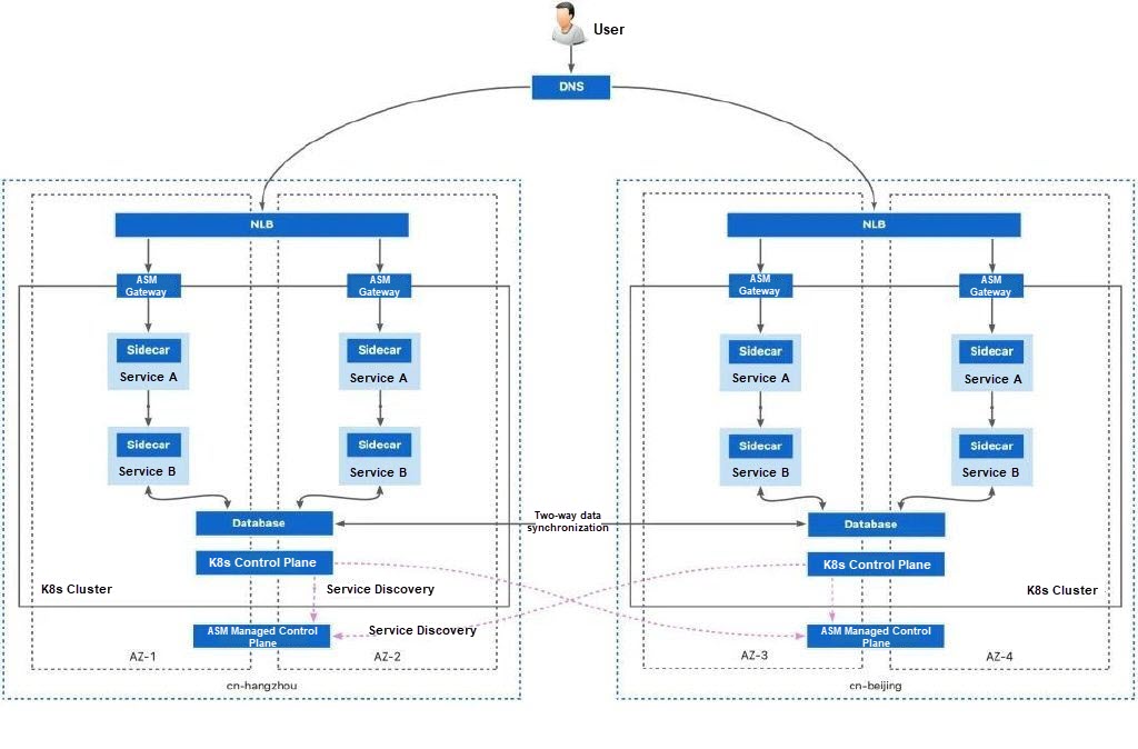
The mesh proxy of ASM continuously checks the response status of each workload to requests and determines whether consecutive response errors of the workload exceed a given threshold. Possible response errors include:
• Service returns 5xx status code.
• Service connection fails.
• Service connection disconnects.
• Service response overruns.
When the number of response errors exceeds the threshold, ASM removes the service from the load balancing pool to redirect requests to other available workloads. Traffic failover is carried out in the following priority order:
If other workloads in the same zone are available, they are prioritized as the traffic target for redirection. If not, workloads in different zones in the same region are selected as the traffic target.
You can also configure a Prometheus instance to collect service mesh metrics. When a failover occurs, you can notify relevant business contacts through metric alerts.
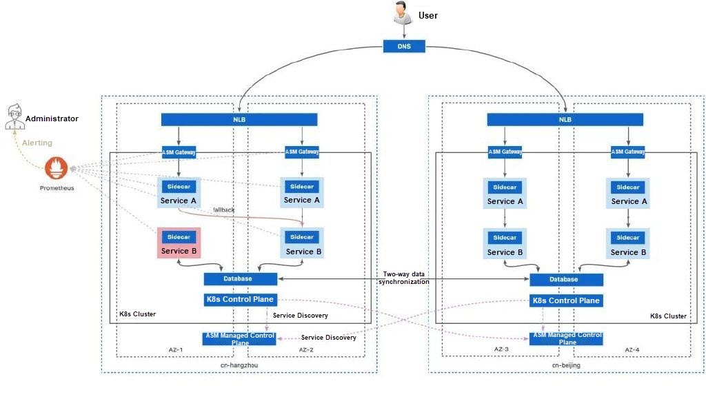
If no workloads are available in any zone in the same region, you can also shift traffic to the same services deployed in other clusters in another region. This process is done automatically by the service mesh.
In this case, you need to rely on the route between the two clusters: pods in cluster A can connect to pods in cluster B. For Alibaba Cloud regions, you can use CEN (Cloud Enterprise Network) to connect physical networks between clusters and implement cluster interconnection. However, you need to pay a higher bandwidth cost.
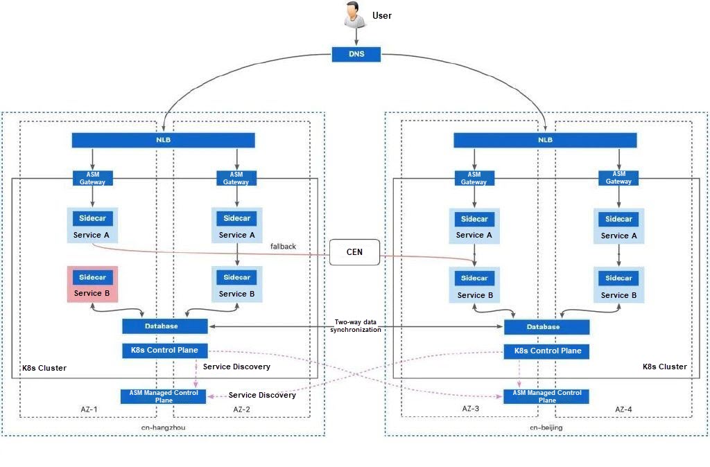
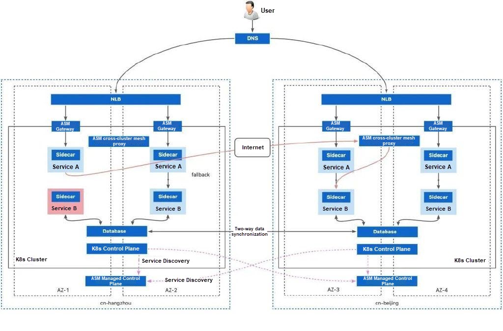
The bandwidth cost of CEN is high. In complex network scenarios, such as an Alibaba Cloud cluster + a hybrid cloud cluster, a hybrid cloud cluster + a hybrid cloud cluster, and a cloud cluster + an on-premises cluster, the physical network often cannot be connected. In these scenarios, ASM allows you to connect clusters over the Internet. By using ASM cross-cluster mesh proxy, you can establish a secure mTLS channel between clusters over the Internet for necessary cross-cluster communication. In this way, secure cross-region traffic redirection can also be achieved.
The geographical location-based failover mechanism of ASM can be seamlessly applied to various application deployment topologies. Different deployment topologies have different support scopes, resource costs, and O&M thresholds. You can select deployment topologies based on actual resource and application conditions.
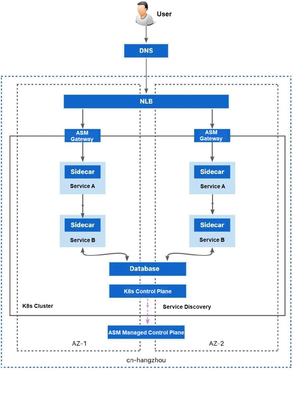
Single-cluster and multi-zone deployment is the simplest deployment solution when considering disaster recovery. ACK supports multi-zone node pools. When you create or run a node pool, we recommend that you select vSwitches residing in different zones for the node pool, and set Scaling Policy to Distribution Balancing. This way, ECS instances can be spread across the zones (vSwitches in the VPC) of the scaling group.
Pros:
• Simple deployment and O&M: You only need to activate an ACK cluster that contains multi-zone node pools and evenly deploy applications in the zones through topology spread constraints.
• Reduced cloud resource consumption: You only need to prepare one copy of cloud resources including load balancers, databases, Kubernetes clusters, and service mesh in the same region.
Cons:
• Insufficient coverage of the fault dimension: It fails to prevent single points of failure in many critical infrastructures and deployments. This deployment topology can handle workload failures caused by zone hardware failures and node hardware failures. However, it cannot handle failures caused by Kubernetes misconfigurations and application dependencies. In addition, it cannot handle region-level faults.
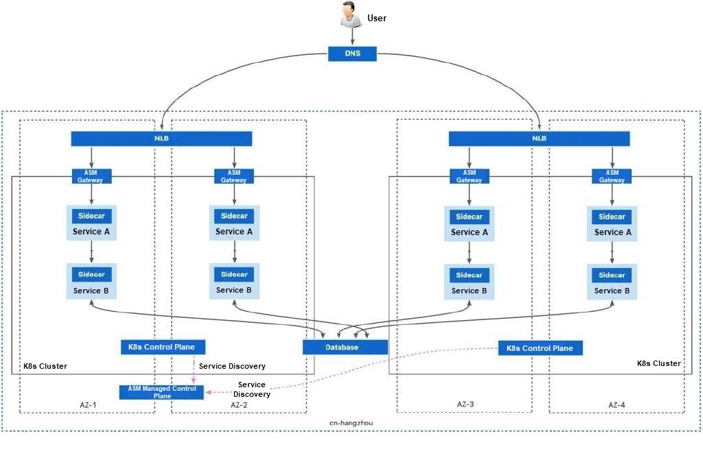
Based on the single-cluster and multi-zone deployment, a single cluster can be changed into multiple clusters, each with its own configuration. Separate configuration can effectively solve the faults caused by the Kubernetes cluster configuration. When a failover occurs, the service mesh will first look for other workloads in the same zone, and then choose one of the other available workloads in different zones in the same region as the failover target.
When deploying applications through such deployment topologies, it is recommended to select separate zones for the two clusters. If the zones of the two clusters overlap, workloads in the same zone may be prioritized over workloads in the same cluster. This may be unexpected for the business.
Pros:
• Compared with single-cluster deployment, this topology expands the coverage of fault causes and further improves the overall system availability.
• Low cost and high quality of cluster interconnection: When you need to fail over traffic to services in another cluster, this deployment topology shows a low cost of cluster interconnection: it only requires that the two clusters are within the same VPC.
Cons:
• High deployment and O&M complexity: You need to deploy services in two Kubernetes clusters.
• Increased cloud resource costs: Multiple copies of cloud resource infrastructures such as load balancers and Kubernetes clusters need to be deployed.
• Inability to handle larger-scale faults: When a region-level fault occurs or all the workloads of a service in a region are unavailable, the topology is unable to address such faults.
In this deployment topology, you need to plan the network configurations of multiple clusters to avoid network conflicts. For more information, see Plan CIDR blocks for multiple clusters on the data plane.
Generally, we recommend that you do not use the multi-cluster, multi-zone, and single-region deployment as the preferred solution because it significantly increases the complexity of deployment and O&M without offering the highest level of availability.
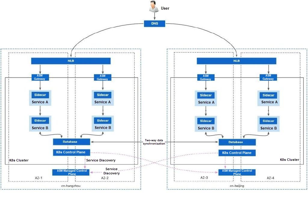
On the basis of multi-cluster deployment, single-region deployment is changed to multi-region deployment. In this way, the deployment of each service is distributed in different dimensions: they have different zones, deployment regions, deployment clusters, and deployment dependencies. This method ensures that there are normal workloads providing services in the event of any possible faults.
Pros:
• High-level availability: The workloads of the same service are distributed to different regions, zones, and clusters as much as possible to maintain service availability to the greatest extent.
Cons:
• High deployment and O&M complexity: You need to deploy services in two Kubernetes clusters and prepare two service mesh instances for less push latency.
• Cluster network connection: Inter-region network connectivity is complex. You can use CEN to connect physical networks between clusters at high bandwidth costs. You can also use ASM cross-cluster mesh proxy to connect them. In this case, network connectivity is based on the Internet and can handle common failover scenarios, but it is not suitable for a large number of cross-cluster calls.
When you have high availability requirements, this topology is recommended for deploying business applications. In the cross-cluster network connection scenario, you can choose one of the following methods to connect the cluster network:
• Connect the underlying network of inter-region clusters by using CEN. To use this method, you should plan the network configurations of multiple clusters to avoid network conflicts. For more information, see Plan CIDR blocks for multiple clusters on the data plane. Next, you need to use CEN to connect the inter-region network. For more information, see Manage inter-region connections.
• Cross-cluster network connectivity and failover are implemented by using ASM cross-cluster mesh proxy to reduce resource costs and solve complex network interconnection issues. In this mode, the networks of the two clusters do not directly interconnect with each other, and no cluster network planning is required. For more information about ASM cross-cluster mesh proxy, see Use ASM cross-cluster mesh proxy to implement cross-network communication among multiple clusters.
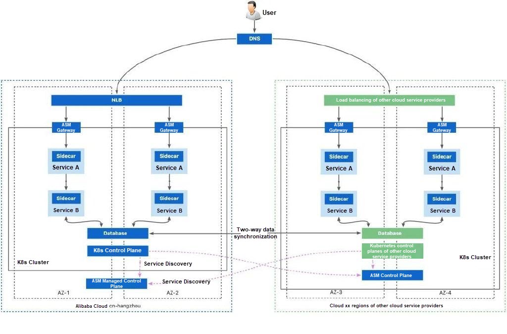
This deployment topology represents the highest level of deployment topology. By providing two sets of Kubernetes clusters among different cloud service providers or between the cloud and on-premises data center, if the infrastructure provided by a single cloud service provider fails, the infrastructure of other cloud service providers can serve normally.
ASM allows you to manage all Kubernetes clusters of other cloud service providers and on-premises data centers. ASM cross-cluster mesh proxy can be used for cluster communication. As long as the cluster can connect to the Internet, you can build a high-availability system based on multiple Kubernetes clusters. The basic environment of a multi-cloud deployment topology is similar to that of multi-region and multi-cluster deployment. However, ASM cannot provide a managed control plane in a non-Alibaba Cloud environment. You can use the ASM remote control plane to solve the push latency issue of service mesh across clouds. For more information, see Reduce push latency using ASM remote control plane.
Pros:
• High-level availability: The workloads of the same service are distributed to different regions, zones, clusters, and cloud service providers as much as possible to maintain service availability to the greatest extent.
Cons:
• Highest complexity of deployment and O&M: Services need to be deployed in two Kubernetes clusters. In addition, due to differences in infrastructure and cloud product capabilities among cloud service providers, deployment in a multi-cloud environment may encounter a large number of compatibility and other unknown issues.
• Cluster network connection: Inter-region network connectivity is complex. You can use CEN to connect physical networks between clusters at high bandwidth costs and there may be network conflicts that prevent connectivity. In this case, you can use the ASM cross-cluster mesh proxy to connect networks. The network connectivity can handle cross-cluster calls for failover based on the Internet.
In a multi-cloud deployment topology, you can also refer to the network connection solution for inter-region clusters.
The article uses the recommended multi-cluster and multi-region deployment method as an example to show how to implement service-level disaster recovery.
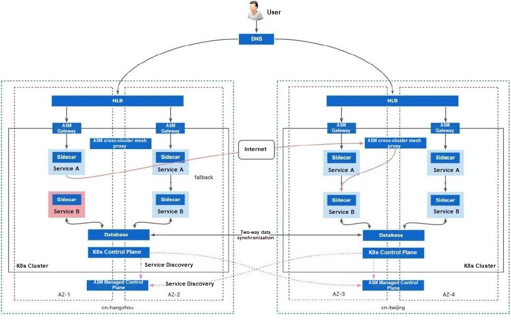
First, deploy two multi-zone Kubernetes clusters in two regions.
Create two Kubernetes clusters named cluster-1 and cluster-2. Enable Expose API Server with EIP. When creating clusters, specify two different regions for cluster-1 and cluster-2.
You should also select vSwitches from multiple zones to support multiple zones of the cluster. Keep the default settings for other configurations and the node pool uses the evenly distributed scaling policy by default.
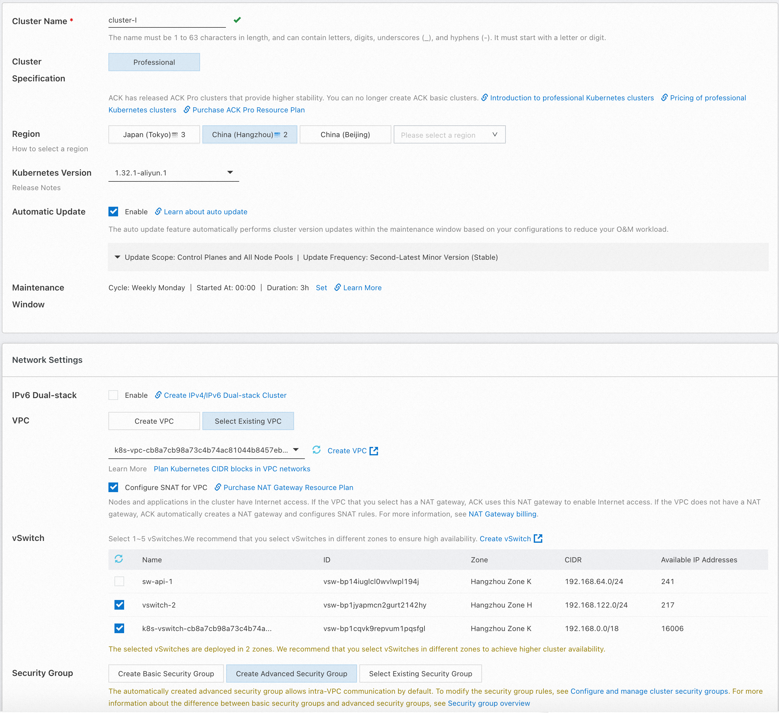
For more information, see Create an ACK managed cluster.
After the Kubernetes clusters are created, you must create ASM instances and add the Kubernetes clusters to ASM for management.
The multi-master control plane architecture is an architecture mode that uses service mesh to manage multiple Kubernetes clusters. In the architecture, multiple service mesh instances manage the data plane components of their respective Kubernetes clusters and distribute configurations for the mesh proxies in the clusters. At the same time, these instances rely on a shared trusted root certificate for service discovery and communication across clusters.
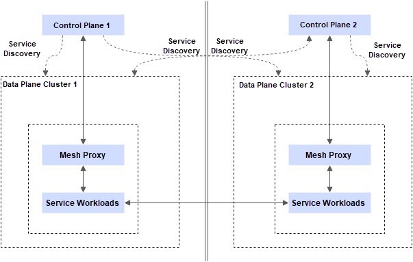
In an inter-region cluster deployment environment, although both clusters can be managed through a unified service mesh instance, building service mesh with a multi-master control plane architecture is still the best practice for inter-region disaster recovery solutions due to the following reasons:
1. Better configuration push latency performance: In the case of inter-region deployment, multiple service mesh instances are used to connect to the mesh proxy in the nearest Kubernetes cluster to achieve better configuration push performance.
2. Better stability performance: When an extreme fault of region unavailability occurs, a service mesh control plane connects to all clusters, and the cluster may not be configured or started synchronously because it cannot connect to the control plane. However, in the multi-master control plane architecture, mesh proxies in normal regions can still connect to the control plane normally without affecting the distribution of service mesh configuration and the normal startup of mesh proxies. This ensures that the ASM gateway and business services in the normal region can be scaled out even if the service mesh control plane in the failed region cannot be connected.
For more information about how to build service mesh with a multi-master control plane architecture, see Multi-cluster disaster recovery through ASM multi-master control plane architecture and complete Steps 1, 2, and 3. After the cluster is created, you will get two service mesh instances named mesh-1 and mesh-2. Both instances perform service discovery on all clusters and configure multi-cluster networks to ensure inter-cluster access.
When creating each service mesh instance, you must select multiple zones corresponding to the cluster to ensure the high availability of the instance itself. Specifically, when creating the service mesh instance, you need to select two vSwitches from two different zones.
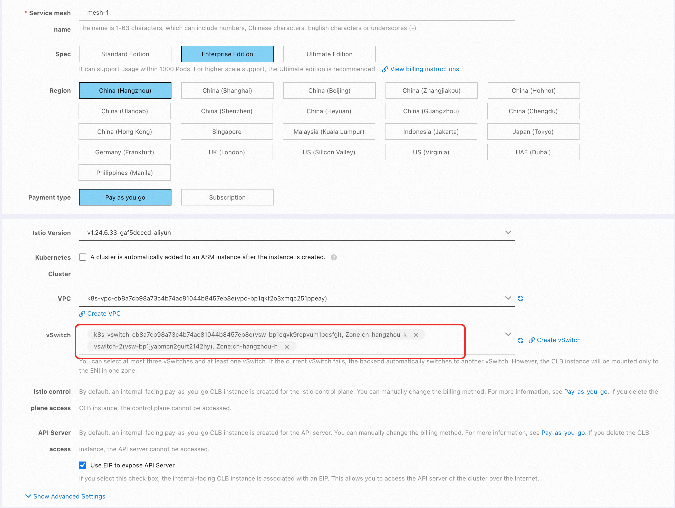
1) Refer to Associate an NLB instance with an ingress gateway, create an ASM gateway named ingressgateway in ASM instances mesh-1 and mesh-2, and associate an NLB instance. Select the same two zones as those of the ASM instance and the ACK cluster for the NLB instance.
In this example, the ASM gateway associated with the NLB instance is used as the traffic ingress. You can also use an ALB instance as the traffic ingress of your application. ALB also provides multi-zone disaster recovery capabilities.
After you create two ASM gateways, record the NLB domain names associated with the two ASM gateways.
2) Enable automatic sidecar proxy injection by default for the namespace in ASM instances mesh-1 and mesh-2. For more information, see Enable automatic sidecar proxy injection.
3) Deploy the sample application in both ACK clusters.
Use kubectl to connect to cluster-1. For more information, see Obtain the kubeconfig file of a cluster and use kubectl to connect to the cluster. Then, run the following command to deploy the sample application.
kubectl apply -f- <<EOF
apiVersion: v1
kind: Service
metadata:
  name: mocka
  labels:
    app: mocka
    service: mocka
spec:
  ports:
  - port: 8000
    name: http
  selector:
    app: mocka
---
apiVersion: apps/v1
kind: Deployment
metadata:
  name: mocka-cn-hangzhou-h
  labels:
    app: mocka
spec:
  replicas: 1
  selector:
    matchLabels:
      app: mocka
  template:
    metadata:
      labels:
        app: mocka
        locality: cn-hangzhou-h
    spec:
      nodeSelector:
        topology.kubernetes.io/zone: cn-hangzhou-h
      containers:
      - name: default
        image: registry-cn-hangzhou.ack.aliyuncs.com/ack-demo/go-http-sample:tracing
        imagePullPolicy: IfNotPresent
        env:
        - name: version
          value: cn-hangzhou-h
        - name: app
          value: mocka
        - name: upstream_url
          value: "http://mockb:8000/"
        ports:
        - containerPort: 8000
---
apiVersion: apps/v1
kind: Deployment
metadata:
  name: mocka-cn-hangzhou-k
  labels:
    app: mocka
spec:
  replicas: 1
  selector:
    matchLabels:
      app: mocka
  template:
    metadata:
      labels:
        app: mocka
        locality: cn-hangzhou-k
    spec:
      nodeSelector:
        topology.kubernetes.io/zone: cn-hangzhou-k
      containers:
      - name: default
        image: registry-cn-hangzhou.ack.aliyuncs.com/ack-demo/go-http-sample:tracing
        imagePullPolicy: IfNotPresent
        env:
        - name: version
          value: cn-hangzhou-k
        - name: app
          value: mocka
        - name: upstream_url
          value: "http://mockb:8000/"
        ports:
        - containerPort: 8000
---
apiVersion: v1
kind: Service
metadata:
  name: mockb
  labels:
    app: mockb
    service: mockb
spec:
  ports:
  - port: 8000
    name: http
  selector:
    app: mockb
---
apiVersion: apps/v1
kind: Deployment
metadata:
  name: mockb-cn-hangzhou-h
  labels:
    app: mockb
spec:
  replicas: 1
  selector:
    matchLabels:
      app: mockb
  template:
    metadata:
      labels:
        app: mockb
        locality: cn-hangzhou-h
    spec:
      nodeSelector:
        topology.kubernetes.io/zone: cn-hangzhou-h
      containers:
      - name: default
        image: registry-cn-hangzhou.ack.aliyuncs.com/ack-demo/go-http-sample:tracing
        imagePullPolicy: IfNotPresent
        env:
        - name: version
          value: cn-hangzhou-h
        - name: app
          value: mockb
        - name: upstream_url
          value: "http://mockc:8000/"
        ports:
        - containerPort: 8000
---
apiVersion: apps/v1
kind: Deployment
metadata:
  name: mockb-cn-hangzhou-k
  labels:
    app: mockb
spec:
  replicas: 1
  selector:
    matchLabels:
      app: mockb
  template:
    metadata:
      labels:
        app: mockb
        locality: cn-hangzhou-k
    spec:
      nodeSelector:
        topology.kubernetes.io/zone: cn-hangzhou-k
      containers:
      - name: default
        image: registry-cn-hangzhou.ack.aliyuncs.com/ack-demo/go-http-sample:tracing
        imagePullPolicy: IfNotPresent
        env:
        - name: version
          value: cn-hangzhou-k
        - name: app
          value: mockb
        - name: upstream_url
          value: "http://mockc:8000/"
        ports:
        - containerPort: 8000
---
apiVersion: v1
kind: Service
metadata:
  name: mockc
  labels:
    app: mockc
    service: mockc
spec:
  ports:
  - port: 8000
    name: http
  selector:
    app: mockc
---
apiVersion: apps/v1
kind: Deployment
metadata:
  name: mockc-cn-hangzhou-h
  labels:
    app: mockc
spec:
  replicas: 1
  selector:
    matchLabels:
      app: mockc
  template:
    metadata:
      labels:
        app: mockc
        locality: cn-hangzhou-h
    spec:
      nodeSelector:
        topology.kubernetes.io/zone: cn-hangzhou-h
      containers:
      - name: default
        image: registry-cn-hangzhou.ack.aliyuncs.com/ack-demo/go-http-sample:tracing
        imagePullPolicy: IfNotPresent
        env:
        - name: version
          value: cn-hangzhou-h
        - name: app
          value: mockc
        ports:
        - containerPort: 8000
---
apiVersion: apps/v1
kind: Deployment
metadata:
  name: mockc-cn-hangzhou-k
  labels:
    app: mockc
spec:
  replicas: 1
  selector:
    matchLabels:
      app: mockc
  template:
    metadata:
      labels:
        app: mockc
        locality: cn-hangzhou-k
    spec:
      nodeSelector:
        topology.kubernetes.io/zone: cn-hangzhou-k
      containers:
      - name: default
        image: registry-cn-hangzhou.ack.aliyuncs.com/ack-demo/go-http-sample:tracing
        imagePullPolicy: IfNotPresent
        env:
        - name: version
          value: cn-hangzhou-k
        - name: app
          value: mockc
        ports:
        - containerPort: 8000
---
apiVersion: networking.istio.io/v1beta1
kind: Gateway
metadata:
  name: mocka
  namespace: default
spec:
  selector:
    istio: ingressgateway
  servers:
    - hosts:
        - '*'
      port:
        name: test
        number: 80
        protocol: HTTP
---
apiVersion: networking.istio.io/v1beta1
kind: VirtualService
metadata:
  name: demoapp-vs
  namespace: default
spec:
  gateways:
    - mocka
  hosts:
    - '*'
  http:
    - name: test
      route:
        - destination:
            host: mocka
            port:
              number: 8000
EOF
Use kubectl to connect to cluster-2 and run the following command to deploy the sample application.
kubectl apply -f- <<EOF
apiVersion: v1
kind: Service
metadata:
  name: mocka
  labels:
    app: mocka
    service: mocka
spec:
  ports:
  - port: 8000
    name: http
  selector:
    app: mocka
---
apiVersion: apps/v1
kind: Deployment
metadata:
  name: mocka-ap-northeast-1a
  labels:
    app: mocka
spec:
  replicas: 1
  selector:
    matchLabels:
      app: mocka
  template:
    metadata:
      labels:
        app: mocka
        locality: ap-northeast-1a
    spec:
      nodeSelector:
        topology.kubernetes.io/zone: ap-northeast-1a
      containers:
      - name: default
        image: registry-cn-hangzhou.ack.aliyuncs.com/ack-demo/go-http-sample:tracing
        imagePullPolicy: IfNotPresent
        env:
        - name: version
          value: ap-northeast-1a
        - name: app
          value: mocka
        - name: upstream_url
          value: "http://mockb:8000/"
        ports:
        - containerPort: 8000
---
apiVersion: apps/v1
kind: Deployment
metadata:
  name: mocka-ap-northeast-1b
  labels:
    app: mocka
spec:
  replicas: 1
  selector:
    matchLabels:
      app: mocka
  template:
    metadata:
      labels:
        app: mocka
        locality: ap-northeast-1b
    spec:
      nodeSelector:
        topology.kubernetes.io/zone: ap-northeast-1b
      containers:
      - name: default
        image: registry-cn-hangzhou.ack.aliyuncs.com/ack-demo/go-http-sample:tracing
        imagePullPolicy: IfNotPresent
        env:
        - name: version
          value: ap-northeast-1b
        - name: app
          value: mocka
        - name: upstream_url
          value: "http://mockb:8000/"
        ports:
        - containerPort: 8000
---
apiVersion: v1
kind: Service
metadata:
  name: mockb
  labels:
    app: mockb
    service: mockb
spec:
  ports:
  - port: 8000
    name: http
  selector:
    app: mockb
---
apiVersion: apps/v1
kind: Deployment
metadata:
  name: mockb-ap-northeast-1a
  labels:
    app: mockb
spec:
  replicas: 1
  selector:
    matchLabels:
      app: mockb
  template:
    metadata:
      labels:
        app: mockb
        locality: ap-northeast-1a
    spec:
      nodeSelector:
        topology.kubernetes.io/zone: ap-northeast-1a
      containers:
      - name: default
        image: registry-cn-hangzhou.ack.aliyuncs.com/ack-demo/go-http-sample:tracing
        imagePullPolicy: IfNotPresent
        env:
        - name: version
          value: ap-northeast-1a
        - name: app
          value: mockb
        - name: upstream_url
          value: "http://mockc:8000/"
        ports:
        - containerPort: 8000
---
apiVersion: apps/v1
kind: Deployment
metadata:
  name: mockb-ap-northeast-1b
  labels:
    app: mockb
spec:
  replicas: 1
  selector:
    matchLabels:
      app: mockb
  template:
    metadata:
      labels:
        app: mockb
        locality: ap-northeast-1b
    spec:
      nodeSelector:
        topology.kubernetes.io/zone: ap-northeast-1b
      containers:
      - name: default
        image: registry-cn-hangzhou.ack.aliyuncs.com/ack-demo/go-http-sample:tracing
        imagePullPolicy: IfNotPresent
        env:
        - name: version
          value: ap-northeast-1b
        - name: app
          value: mockb
        - name: upstream_url
          value: "http://mockc:8000/"
        ports:
        - containerPort: 8000
---
apiVersion: v1
kind: Service
metadata:
  name: mockc
  labels:
    app: mockc
    service: mockc
spec:
  ports:
  - port: 8000
    name: http
  selector:
    app: mockc
---
apiVersion: apps/v1
kind: Deployment
metadata:
  name: mockc-ap-northeast-1a
  labels:
    app: mockc
spec:
  replicas: 1
  selector:
    matchLabels:
      app: mockc
  template:
    metadata:
      labels:
        app: mockc
        locality: ap-northeast-1a
    spec:
      nodeSelector:
        topology.kubernetes.io/zone: ap-northeast-1a
      containers:
      - name: default
        image: registry-cn-hangzhou.ack.aliyuncs.com/ack-demo/go-http-sample:tracing
        imagePullPolicy: IfNotPresent
        env:
        - name: version
          value: ap-northeast-1a
        - name: app
          value: mockc
        ports:
        - containerPort: 8000
---
apiVersion: apps/v1
kind: Deployment
metadata:
  name: mockc-ap-northeast-1b
  labels:
    app: mockc
spec:
  replicas: 1
  selector:
    matchLabels:
      app: mockc
  template:
    metadata:
      labels:
        app: mockc
        locality: ap-northeast-1b
    spec:
      nodeSelector:
        topology.kubernetes.io/zone: ap-northeast-1b
      containers:
      - name: default
        image: registry-cn-hangzhou.ack.aliyuncs.com/ack-demo/go-http-sample:tracing
        imagePullPolicy: IfNotPresent
        env:
        - name: version
          value: ap-northeast-1b
        - name: app
          value: mockc
        ports:
        - containerPort: 8000
---
apiVersion: networking.istio.io/v1beta1
kind: Gateway
metadata:
  name: mocka
  namespace: default
spec:
  selector:
    istio: ingressgateway
  servers:
    - hosts:
        - '*'
      port:
        name: test
        number: 80
        protocol: HTTP
---
apiVersion: networking.istio.io/v1beta1
kind: VirtualService
metadata:
  name: demoapp-vs
  namespace: default
spec:
  gateways:
    - mocka
  hosts:
    - '*'
  http:
    - name: test
      route:
        - destination:
            host: mocka
            port:
              number: 8000
EOF
The preceding two commands deploy an application that contains services named mocka, mockb, and mockc in two clusters. Each service contains two stateless deployments with only one replica. They are distributed to nodes in different zones through different nodeSelectors and return their zones by configuring environment variables. In this example, workloads are deployed in two regions and four zones of Alibaba Cloud: cn-hangzhou-h, cn-hangzhou-k, ap-northeast-1a, and ap-northeast-1b.
When the application is accessed, the pod information on the entire trace of the application is responded to. For example:
-> mocka(version: cn-hangzhou-h, ip: 192.168.122.66)-> mockb(version: cn-hangzhou-k, ip: 192.168.0.47)-> mockc(version: cn-hangzhou-h, ip: 192.168.122.44)%The example directly uses the nodeSelector field of the pod to manually select the zone where the pod is located. This is for the purpose of the intuitive demonstration. In the actual construction of a high-availability environment, you should configure topology spread constraints to ensure that pods are distributed in different zones as much as possible.
For more information, see Workload HA configuration.
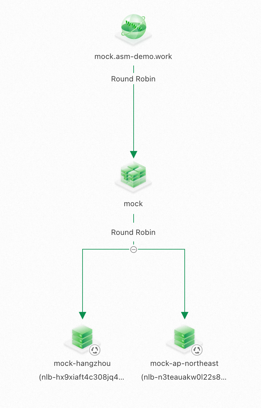
You can configure GTM and combine two NLB instances associated with two ASM gateways to implement multi-active disaster recovery for the ingress gateway. In normal cases, the application domain name can be resolved to the domain names of two NLB instances through a CNAME record in the way of 1:1. For more information, see Use GTM to implement multi-active load balancing and disaster recovery.
The geographical location-based failover capability of ASM is enabled by default, but it does not take effect until you specify the host-level circuit breaking rule in the destination rule section.
Use kubectl to connect to cluster-1 and cluster-2. For more information, see Obtain the kubeconfig file of a cluster and use kubectl to connect to the cluster. Then, run the following command to deploy the host-level circuit breaking rules for the mocka, mockb, and mockc services.
kubectl apply -f- <<EOF
apiVersion: networking.istio.io/v1beta1
kind: DestinationRule
metadata:
  name: mocka
spec:
  host: mocka
  trafficPolicy:
    outlierDetection:
      splitExternalLocalOriginErrors: true
      consecutiveLocalOriginFailures: 1
      baseEjectionTime: 5m
      consecutive5xxErrors: 1
      interval: 30s
      maxEjectionPercent: 100
---
apiVersion: networking.istio.io/v1beta1
kind: DestinationRule
metadata:
  name: mockb
spec:
  host: mockb
  trafficPolicy:
    outlierDetection:
      splitExternalLocalOriginErrors: true
      consecutiveLocalOriginFailures: 1
      baseEjectionTime: 5m
      consecutive5xxErrors: 1
      interval: 30s
      maxEjectionPercent: 100
---
apiVersion: networking.istio.io/v1beta1
kind: DestinationRule
metadata:
  name: mockc
spec:
  host: mockc
  trafficPolicy:
    outlierDetection:
      splitExternalLocalOriginErrors: true
      consecutiveLocalOriginFailures: 1
      baseEjectionTime: 5m
      consecutive5xxErrors: 1
      interval: 30s
      maxEjectionPercent: 100
EOF
The outlierDetection is a mechanism of service mesh for detecting service faults and evicting faulty endpoints. The following table gives explanations.
| interval | The length of time window for fault detection |
|---|---|
| baseEjectionTime | Eject the endpoint determined to be faulty from the load balancing pool |
| maxEjectionPercent | Maximum ejected endpoint ratio |
| consecutive5xxErrors | The number of consecutive 5xx errors returned before the endpoint is determined to be faulty |
| splitExternalLocalOriginErrors | Whether to count connection failures and connection timeout as faults |
| consecutiveLocalOriginFailures | The number of consecutive non-5xx errors (connection failures and connection timeout) before the endpoint is determined to be faulty |
After a destination rule is created to implement the automatic fault detection mechanism for host-level circuit breaking, the geographical location-based failover mechanism of the service mesh takes effect. In this case, the default call method is the Intra-zone Provider First.
Try to request the service domain name. The expected output is as follows:
curl mock.asm-demo.work/mock -v
* Host mock.asm-demo.work:80 was resolved.
* IPv6: (none)
* IPv4: 8.209.247.47, 8.221.138.42
*   Trying 8.209.247.47:80...
* Connected to mock.asm-demo.work (8.209.247.47) port 80
> GET /mock HTTP/1.1
> Host: mock.asm-demo.work
> User-Agent: curl/8.7.1
> Accept: */*
>
* Request completely sent off
< HTTP/1.1 200 OK
< date: Wed, 11 Dec 2024 12:10:56 GMT
< content-length: 153
< content-type: text/plain; charset=utf-8
< x-envoy-upstream-service-time: 3
< server: istio-envoy
<
* Connection #0 to host mock.asm-demo.work left intact
-> mocka(version: ap-northeast-1b, ip: 10.1.225.40)-> mockb(version: ap-northeast-1b, ip: 10.1.225.31)-> mockc(version: ap-northeast-1b, ip: 10.1.225.32)%
You can see that the service trace always remains on the workload in the same zone.
You can modify the container image in a zone of the mockb service to simulate some workload faults of the service.
Log on to the ACK console and find a mockb deployment in a cluster. This example selects mockb-ap-northeast-1a in cluster-2. Click Edit in the Actions column and replace the image content and startup command to simulate the situation where the developer issues incorrect commands.
Change the image name to registry.cn-hangzhou.aliyuncs.com/acs/curl:8.1.2. After the container image is started, it does not listen on any port. Therefore, any access to the container will fail to connect.
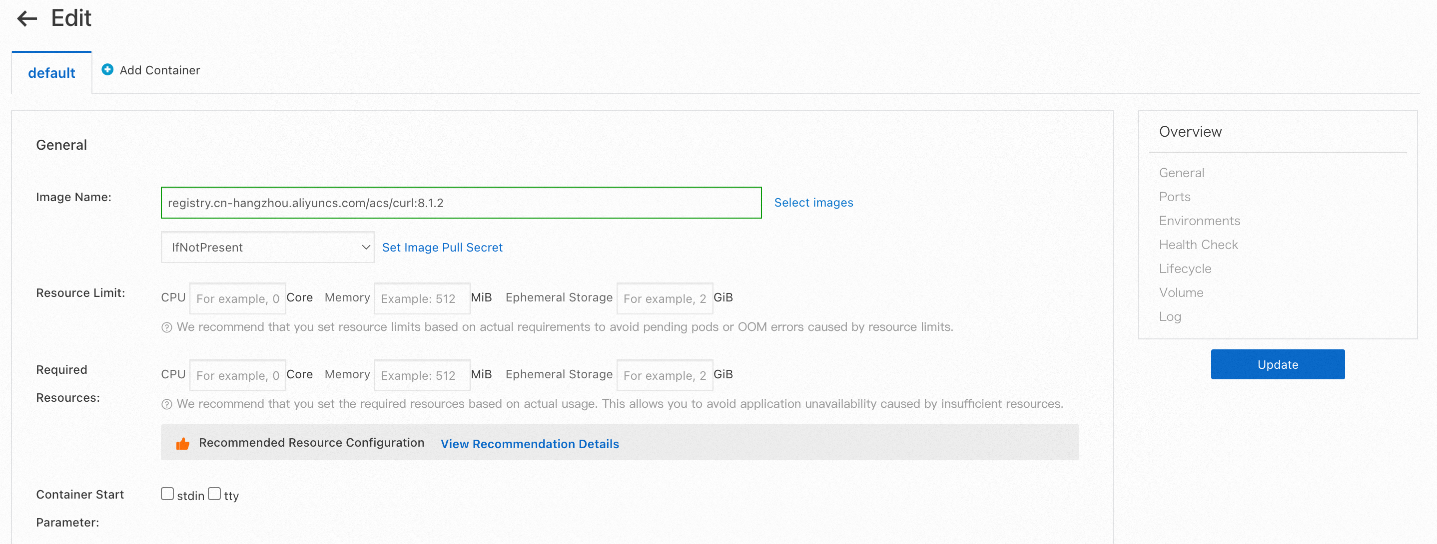
Add the startup command sleep 3600 to the container so that it can start normally.

After the modification, continue to access the application domain name to rehearse the situation when a fault occurs.
When a request is sent to a zone other than ap-northeast-1a, you can see that the request remains in the normal zone.
curl mock.asm-demo.work/mock -v
* Host mock.asm-demo.work:80 was resolved.
* IPv6: (none)
* IPv4: 8.209.247.47, 8.221.138.42
*   Trying 8.209.247.47:80...
* Connected to mock.asm-demo.work (8.209.247.47) port 80
> GET /mock HTTP/1.1
> Host: mock.asm-demo.work
> User-Agent: curl/8.7.1
> Accept: */*
>
* Request completely sent off
< HTTP/1.1 200 OK
< date: Wed, 11 Dec 2024 12:10:56 GMT
< content-length: 153
< content-type: text/plain; charset=utf-8
< x-envoy-upstream-service-time: 3
< server: istio-envoy
<
* Connection #0 to host mock.asm-demo.work left intact
-> mocka(version: ap-northeast-1b, ip: 10.1.225.40)-> mockb(version: ap-northeast-1b, ip: 10.1.225.31)-> mockc(version: ap-northeast-1b, ip: 10.1.225.32)%
When the request is sent to the ap-northeast-1a zone, the first request will find that the connection is rejected when the request accesses the mockb service.
curl mock.asm-demo.work/mock -v
* Host mock.asm-demo.work:80 was resolved.
* IPv6: (none)
* IPv4: 112.124.65.120, 121.41.238.104
*   Trying 112.124.65.120:80...
* Connected to mock.asm-demo.work (112.124.65.120) port 80
> GET /mock HTTP/1.1
> Host: mock.asm-demo.work
> User-Agent: curl/8.7.1
> Accept: */*
>
* Request completely sent off
< HTTP/1.1 200 OK
< date: Wed, 11 Dec 2024 12:08:45 GMT
< content-length: 220
< content-type: text/plain; charset=utf-8
< x-envoy-upstream-service-time: 48
< server: istio-envoy
<
* Connection #0 to host mock.asm-demo.work left intact
-> mocka(version: cn-hangzhou-h, ip: 192.168.122.135)upstream connect error or disconnect/reset before headers. reset reason: remote connection failure, transport failure reason: delayed connect error: Connection refused%
When the request is sent to the ap-northeast-1a zone again, you can find that the service requested after mocka has failed over, and has been preferentially transferred to ap-northeast-1b in a different zone in the same region. Failover will occur automatically through the detection of a fault by host-level circuit breaking.
curl mock.asm-demo.work/mock -v
* Host mock.asm-demo.work:80 was resolved.
* IPv6: (none)
* IPv4: 8.209.247.47, 8.221.138.42
*   Trying 8.209.247.47:80...
* Connected to mock.asm-demo.work (8.209.247.47) port 80
> GET /mock HTTP/1.1
> Host: mock.asm-demo.work
> User-Agent: curl/8.7.1
> Accept: */*
>
* Request completely sent off
< HTTP/1.1 200 OK
< date: Wed, 11 Dec 2024 12:10:59 GMT
< content-length: 154
< content-type: text/plain; charset=utf-8
< x-envoy-upstream-service-time: 4
< server: istio-envoy
<
* Connection #0 to host mock.asm-demo.work left intact
-> mocka(version: ap-northeast-1a, ip: 10.0.239.141)-> mockb(version: ap-northeast-1b, ip: 10.1.225.31)-> mockc(version: ap-northeast-1b, ip: 10.1.225.32)%Host-level circuit breaking can generate a series of relevant metrics. This helps you determine whether circuit breaking occurs. The following table describes some relevant metrics.
| Metrics | Metric Type | Description |
|---|---|---|
| envoy_cluster_outlier_detection_ejections_active | Gauge | The number of hosts that are ejected |
| envoy_cluster_outlier_detection_ejections_enforced_total | Counter | The number of times that host ejection occurs |
| envoy_cluster_outlier_detection_ejections_overflow | Counter | The number of times that host ejection was abandoned because the maximum ejection percentage was reached |
| ejections_detected_consecutive_5xx | Counter | The number of consecutive 5xx errors detected on a host |
You can configure proxyStatsMatcher of a sidecar proxy to enable the sidecar proxy to report metrics related to circuit breaking. After the configuration, you can use Prometheus to collect and view the metrics.
After you configure metrics related to host-level circuit breaking, you can configure a Prometheus instance to collect the metrics. You can also configure alert rules based on key metrics. This way, alerts are generated when circuit breaking occurs. In this way, relevant contacts are notified in time when a service-level fault occurs, so as to timely monitor the fault and locate the root cause.
The following section describes how to configure metric collection and alerts for host-level circuit breaking. In this example, Managed Service for Prometheus is used.
| Parameters | Examples | Description |
|---|---|---|
| Custom PromQL Statements |
(sum(envoy_cluster_outlier_detection_ejections_active) by(cluster_name, namespace))>0
|
In the example, the envoy_cluster_outlier_detection_ejections_active metric is queried to determine whether a host is being ejected in the current cluster. The query results are grouped by the namespace where the service resides and the service name. |
| Alert Message | Host-level circuit breaking is triggered. Some workloads encounter errors repeatedly and the hosts are ejected from the load balancing pool. Namespace: {{$labels.namespace}}, servicewhere ejection occurs: {{$labels.cluster_name}}. Number of hosts that are ejected: {{ $value }}
|
The alert information in the example shows the namespace of the service that triggers the circuit breaking, the service name, and the number of hosts that are ejected. |

223 posts | 33 followers
FollowAlibaba Container Service - May 23, 2025
Alibaba Container Service - May 23, 2025
Alibaba Developer - August 24, 2021
Alibaba Clouder - February 22, 2021
Xi Ning Wang(王夕宁) - December 16, 2020
Alibaba Container Service - March 12, 2025

223 posts | 33 followers
Follow Container Service for Kubernetes
Alibaba Cloud Container Service for Kubernetes is a fully managed cloud container management service that supports native Kubernetes and integrates with other Alibaba Cloud products.
Learn More ACK One
Provides a control plane to allow users to manage Kubernetes clusters that run based on different infrastructure resources
Learn More Cloud-Native Applications Management Solution
Accelerate and secure the development, deployment, and management of containerized applications cost-effectively.
Learn More CEN
CEN
A global network for rapidly building a distributed business system and hybrid cloud to help users create a network with enterprise level-scalability and the communication capabilities of a cloud network
Learn MoreMore Posts by Alibaba Container Service