By Sheng Dong, Alibaba Cloud After-Sales Technical Expert
There are two solutions available for implementing the Kubernetes cluster network of Alibaba Cloud. One is Flannel and the other is Terway based on Calico and Elastic Network Interfaces (ENIs). Terway and Flannel are similar with an exception that Terway supports pod ENIs and the NetworkPolicy function.
In this article, Flannel is used as an example to analyze the method of implementing the Alibaba Cloud Kubernetes cluster network. This article analyzes the method from the perspectives of network construction and network-based communication and uses the 1.12.6 version for the analysis.
A configured Kubernetes cluster network of Alibaba Cloud consists of the cluster CIDR block, VPC routing table, node network, pod CIDR block of each node, virtual bridge cni0 on nodes, and the veth0 device connecting pods and bridges, as shown in the following figure.
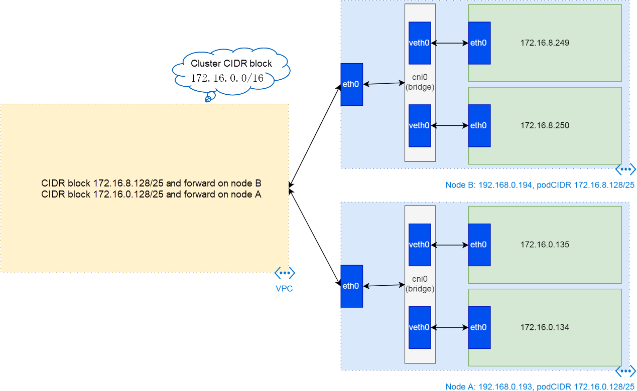
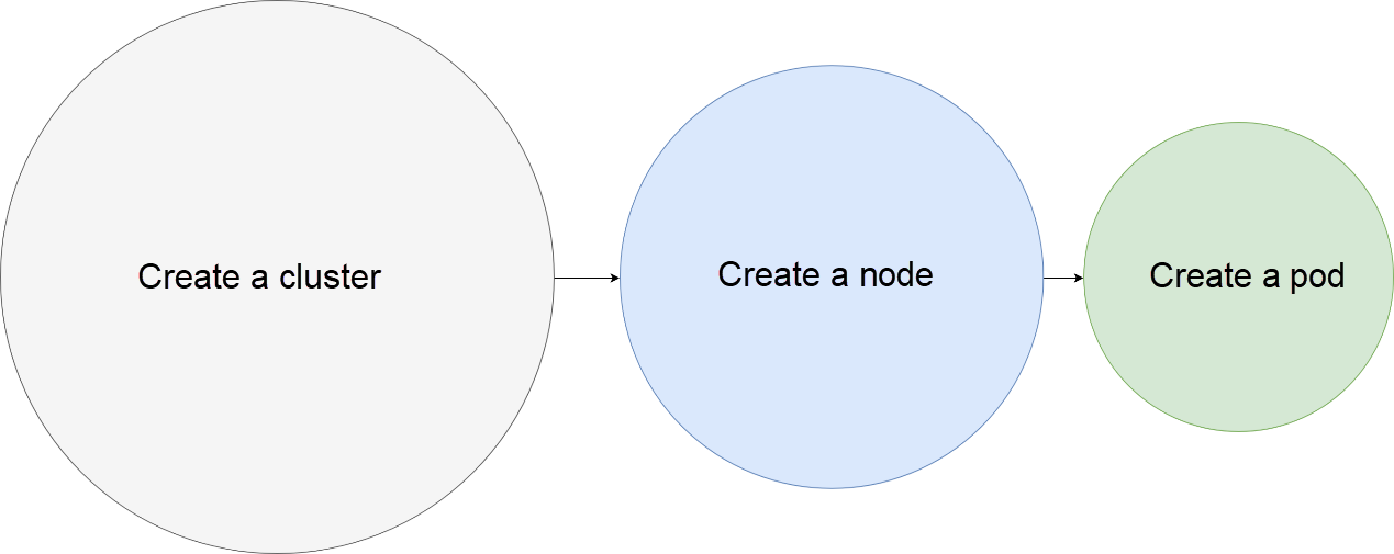
Many other articles contain similar figures. However, it is hard to understand the figures because the related configurations are complex. This article divides the configurations into three parts, including the cluster configuration, node configuration, and pod configuration.
Accordingly, cluster network CIDR blocks are divided into three. First the cluster CIDR block, then the pod CIDR block of each node (the subnet CIDR block of the cluster CIDR block), and finally the pod IP address allocated from a pod CIDR block.
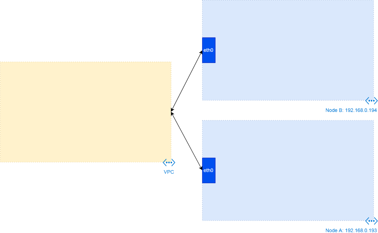
A cluster is created based on Virtual Private Cloud (VPC) and Elastic Compute Service (ECS) instances. After creating VPC and ECS instances, obtain the resource configuration, as shown in the following figure. Obtain one VPC whose CIDR block is 192.168.0.0/16 and several ECS instances whose IP addresses are allocated from the VPC CIDR block.
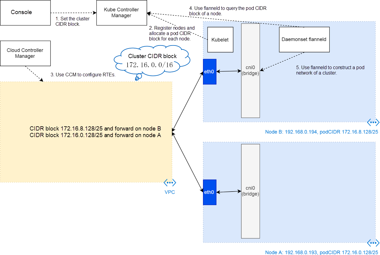
Based on the initial resources, obtain the cluster CIDR block in the cluster creation console. The value is transferred to the provision script on a cluster node as a parameter, and then the script transfers it to kubeadm, a cluster node configuration tool. kubeadm finally writes the parameter to the kube-controller-manager.yaml file of the static pod of the cluster controller.
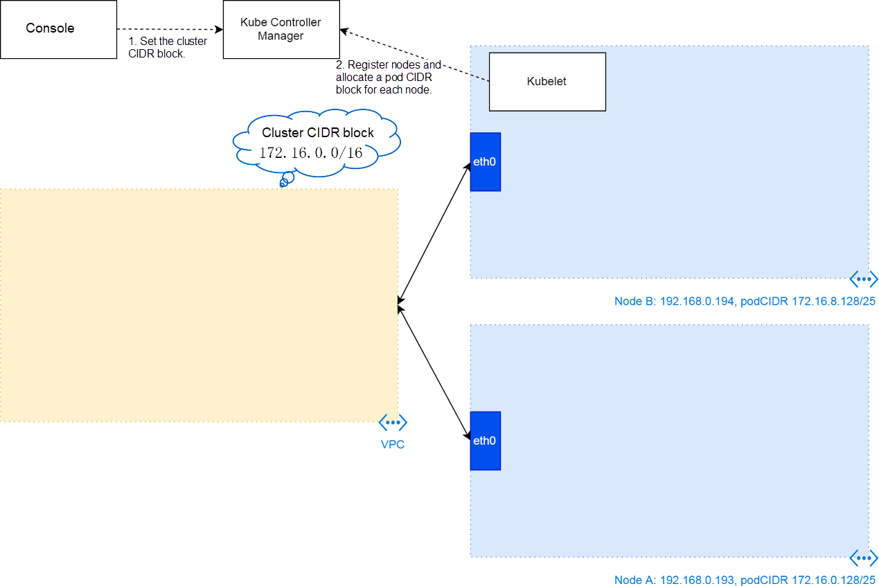
With this parameter, the cluster controller divides a subnet for each registered node when kubelet registers nodes to the cluster. Thus, the cluster controller allocates a pod CIDR block to each node. As shown in the preceding figure, the subnet CIDR block of node B is 172.16.8.1/25 while that of node A is 172.16.0.128/25. The configuration is recorded to pod CIDR block data of cluster nodes.
After the cluster phase, Kubernetes has the cluster CIDR block and pod CIDR block allocated to each node. Accordingly, the cluster delivers a flanneld to each phase to further construct the network framework for the pod on each node. It involves two operations.
One is that the cluster uses the Cloud Controller Manager (CCM) to configure routing table entries (RTEs) for VPC. Each node has one RTE. That is, if the VPC router receives the IP address in a node pod CIDR block, the route forwards the network packet to the corresponding ECS instance.
The other operation is the creation of the cni0 virtual bridge and related routes. The configurations are used to forward external network packets to the virtual local area network (VLAN) of cni0 when the received IP address is in the pod CIDR block.
Note: Actually, cni0 is created by Flannel CNI (described in the next section) when the pod that uses the pod network first is scheduled to the node. However, cni0 belongs to the node network but not the pod network logically.
In the preceding three phases, the cluster constructs network communication channels between pods. In this case, if the cluster schedules a pod to a node, kubelet uses Flannel CNI to create a network namespace and veth devices for the pod, adds a veth device to the cni0 virtual bridge, and configures IP addresses for veth devices in the pod.
The pod is connected to the network communication channels. Note that flanneld in the previous section is different from Flannel CNI in this section. flanneld is a pod that is sent by DaemonSet to each node and is used to construct networks (channels). Flannel CNI is a CNI plug-in installed by the kubernetes-cni RPM package during node creation, and is called by kubelet to construct a network (branch) for a pod.
With a better understanding of the difference between flanneld and Flannel CNI, it is easy to understand the usage of their configuration files. For example, the /run/flannel/subnet.env file is created by flanneld, which is an environment variable file providing input for Flannel CNI. The /etc/cni/net.d/10-flannel.conf file is a subnet configuration file copied by the flanneld pod (actually the install-cni script in the pod) from a pod to a directory on a node for Flannel CNI.
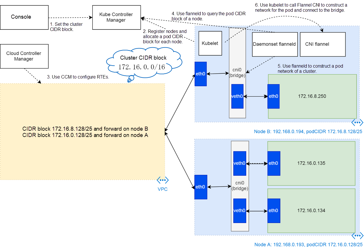
The pod network environment is constructed.
In the network environment, a pod completes the following communication:
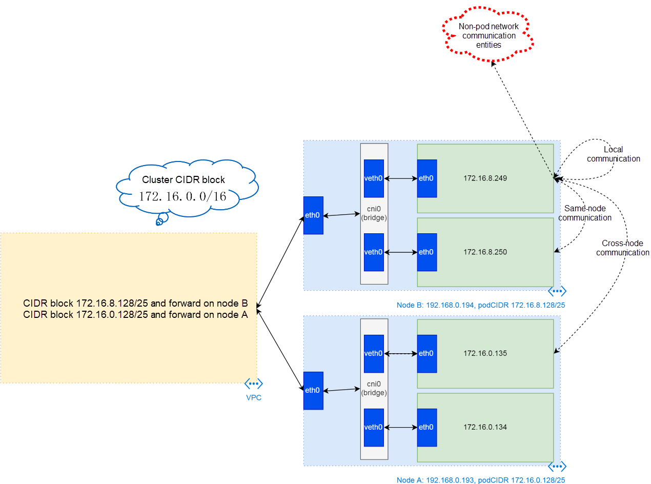
Local communication indicates the communication among containers in a pod. Containers in a pod share a network protocol stack. Therefore, they communicate with each other through loopback.
Same-node pod communication indicates the communication in the cni0 virtual bridge, which is similar to the communication among devices on an L2 LAN.
Cross-node pod communication is a little more complex, but is intuitive. An end data packet is sent to a node through the gateway of the cni0 virtual bridge, and then the node sends the packet to the VPC route through eth0 on the node. In this process, no encapsulation operation is involved. After receiving the data packet, the VPC route queries the routing table to determine the packet destination and then sends the data packet to the corresponding ECS node. flanneld creates a real cni0 route on the node. Therefore, the node sends the data packet to the cni0 LAN of the destination and then to the pod of the destination.
For communication between a pod and non-pod network entities, SNAT needs to be configured based on the iptables rule on a node. The rule indicates that flanneld configures SNAT according to the --ip-masq command line.
This article describes the construction and communication principles of the Kubernetes cluster network of Alibaba Cloud. It further analyzes the Kubernetes cluster network from the perspectives of network construction and communication. Network construction includes the initial phase, cluster phase, node phase, and pod phase, which helps to understand complex configurations. It is easy to understand the cluster communication principle according to the configurations.
From Confused to Proficient: Analysis of Failure to Delete a Kubernetes Cluster Namespace
From Confused to Proficient: Kubernetes Authentication and Scheduling

2,593 posts | 791 followers
FollowAlibaba Clouder - December 19, 2019
Alibaba Clouder - December 19, 2019
Alibaba Clouder - December 19, 2019
Alibaba Clouder - December 19, 2019
Alibaba Clouder - December 19, 2019
Alibaba Clouder - December 19, 2019

2,593 posts | 791 followers
Follow ECS(Elastic Compute Service)
Elastic and secure virtual cloud servers to cater all your cloud hosting needs.
Learn More Container Registry
A secure image hosting platform providing containerized image lifecycle management
Learn More Container Service for Kubernetes
Alibaba Cloud Container Service for Kubernetes is a fully managed cloud container management service that supports native Kubernetes and integrates with other Alibaba Cloud products.
Learn MoreMore Posts by Alibaba Clouder